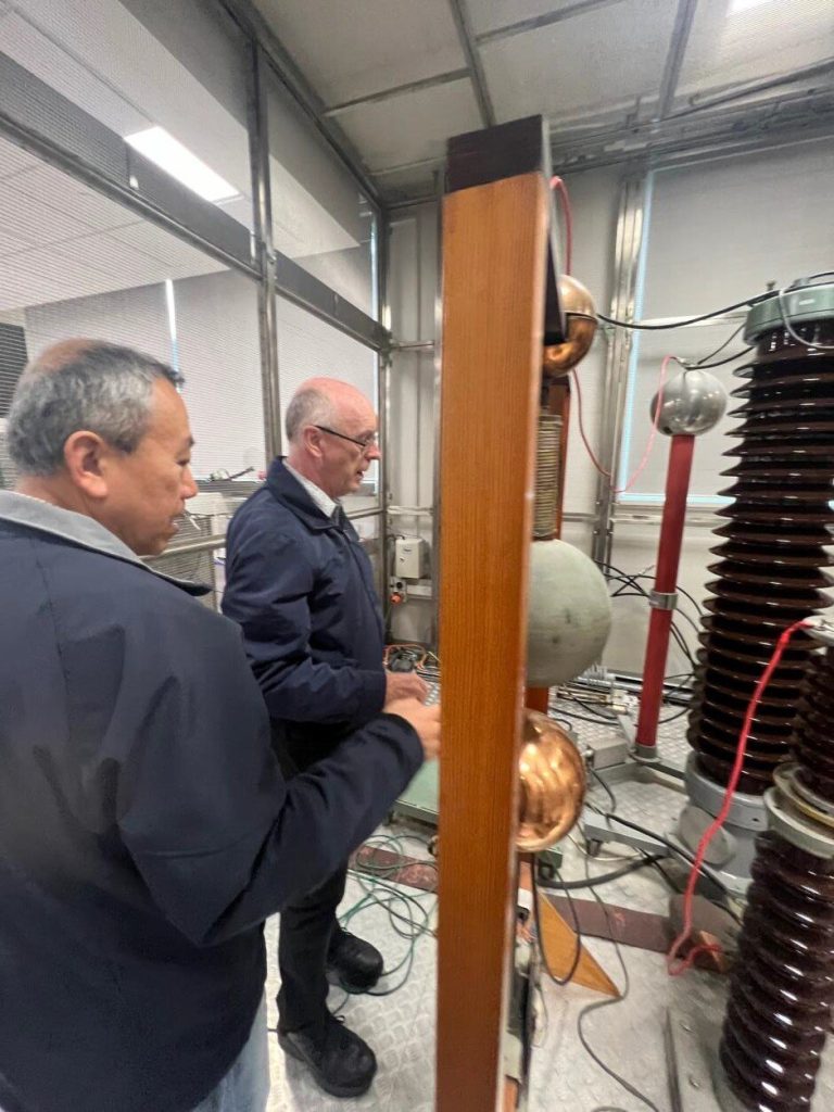
This is a photo record of Impulse Testing during a visit by Tortech staff to the HV Lab at UNSW.
WHAT DID WE DO?
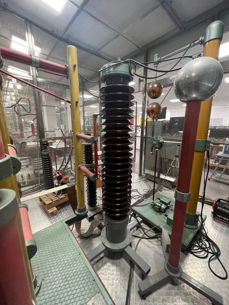
We are testing a 11kv indoor HV voltage transformer epoxy cast at impulse test level of 95kvp.
We are assessing the best way to detect a fault during the impulse test:
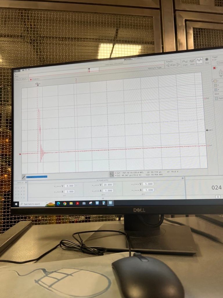
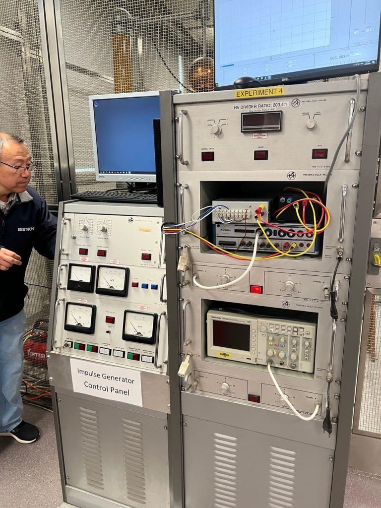
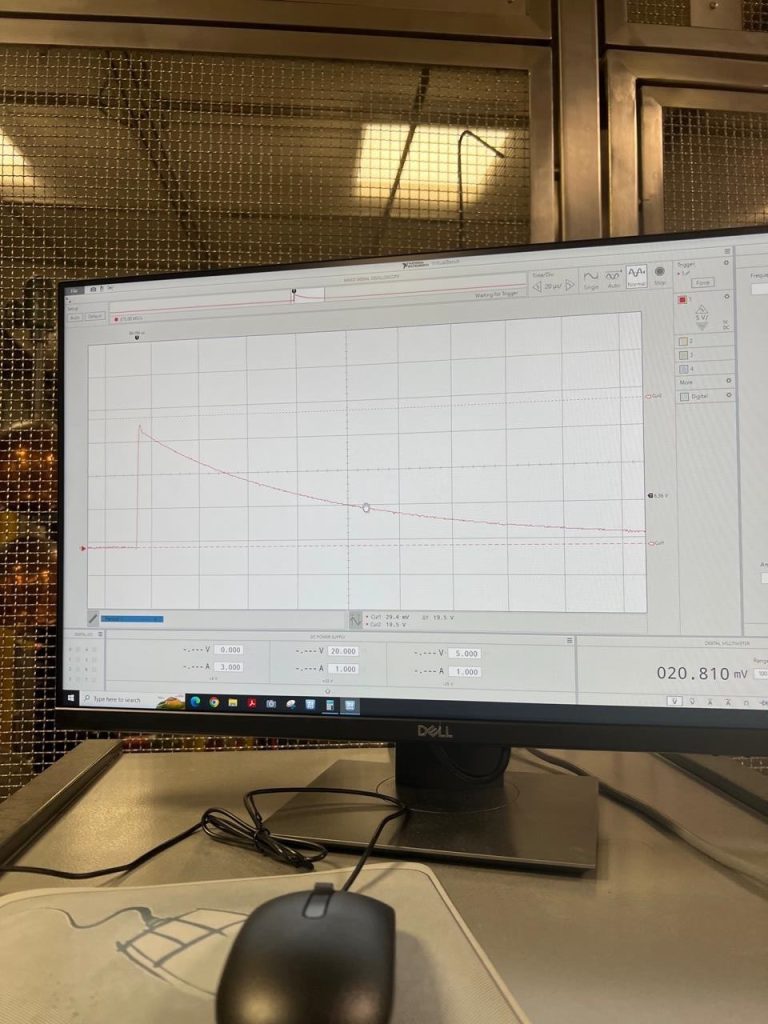
1) Voltage trace on the HV side
2) Current trace
3) Transferred voltage trace on the secondary side
In the case of the magnetic VT, there is a problem in detecting whether or not during the impulse test a breakdown of the insulation material within the transformer has occurred.
WHY?
The volts per turn of the magnetic VT are very low (say 10 volts per turn) vs a power transformer which may have 200v per turn.
This means the faults can be harder to detect in the magnetic VT ,since it could involve smaller proportional changes (voltage or current) in the transformer under test.
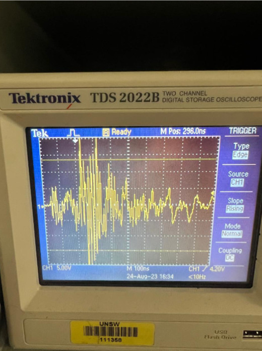
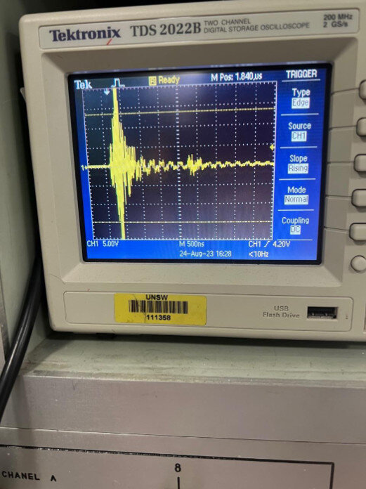
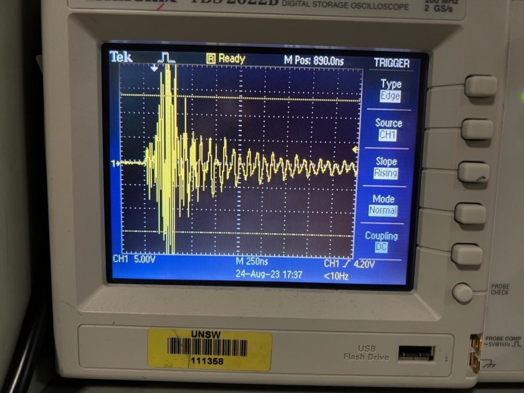
Sparking faults produce high frequency oscillations. This is easy to detect. Solid faults – metal to metal are harder to detect. No oscillations here!
Hence, the smallest fault to be detected is a “solid” fault between two adjacent turns of the winding.
This is where we have to increase the sensitivity of the detection equipment with the “solid” type of fault in the magnetic VT, which is a highly inductive test object.
We also experimented with impulse chop wave testing which is even more onerous on the
insulation structure than the full wave test.
WHY?
The rate of change of voltage with the chop wave test is higher than the full wave test.
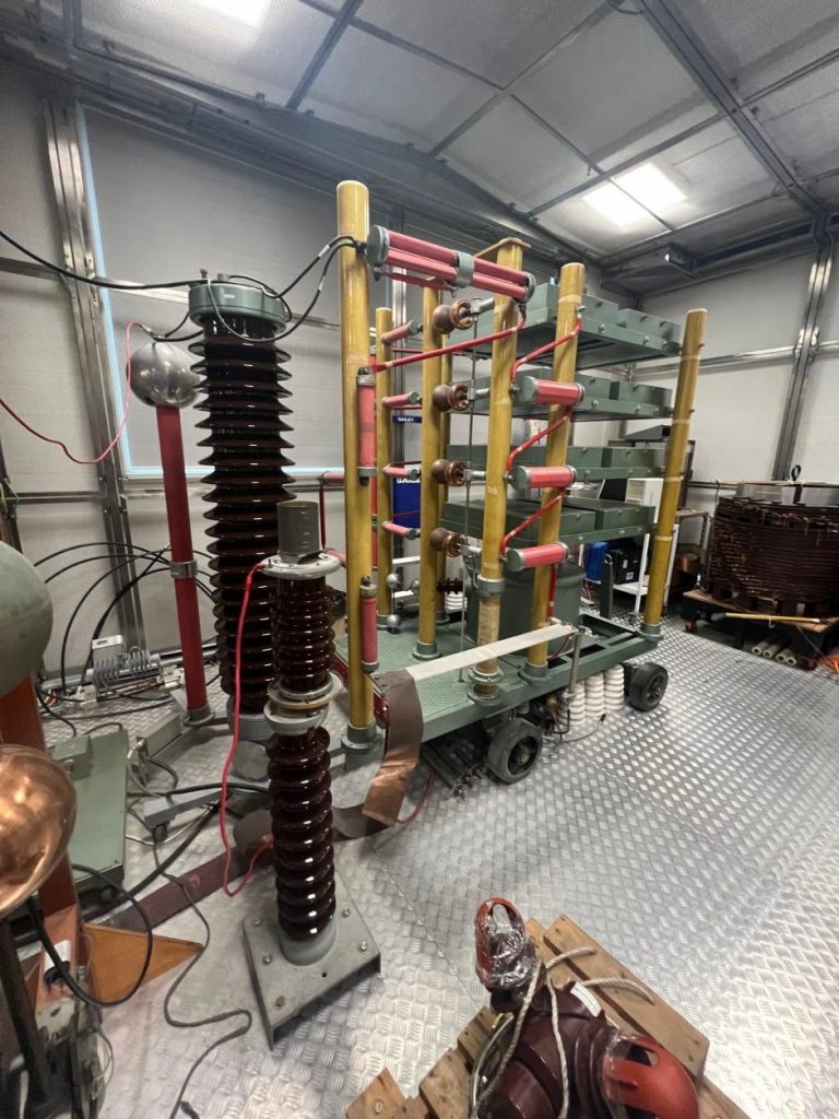
HOW DOES IMPULSE CHOP WAVE TESTING WORK?
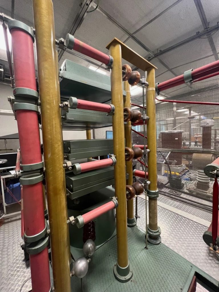
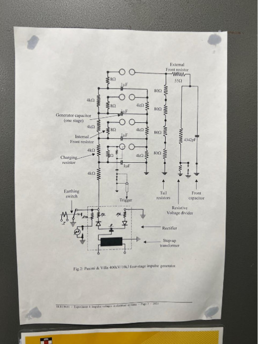
Chop wave impulse testing is controlled by a trigger function that drives a HV pulse from a HV pulse transformer that causes a 10kv voltage to be impressed on a third small electrode that is in the middle of the earthed sphere at the bottom of the chop wave spheres.
HOW DOES THIS HAPPEN?
This small arc triggered by the small electrode ionises the air at the surface of the bottom sphere. This induces the creation of a flashover of the chopping spheres. This controls the point on wave that triggers the chop spheres to chop the impulse waveform. This is normally 2-6 micro seconds from the initialisation of the impulse waveform, to the point of chopping.
You can see examples of chop wave testing in our UNSW visit photos.
This was a unique experience and we thank UNSW School of Elec Eng. for the opportunity to visit
the HV Lab.